The problem with having a
supercharger that is spinning much faster than it is designed to
is that a lot of heat is generated, particularly so as the
efficiency drops. The supercharger on the MR2 is a Roots type
which is very good for mid-range torque and makes a very driveable
car, but the problem is as the revs rise that the blower starts to
turn into something of a hairdryer.
Obviously the MR2 is intercooled
as standard, though being a mid-engined car the intercooler is in
fact in the engine bay. The idea being that air is drawn up
through the engine bay, through the intercooler and out the top of
the engine lid where there is a low pressure area due to airflow
from the roof over the engine lid.
With standard boost (around 8psi)
this is generally fine, but when you are running around 12-13psi
the air coming through the intercooler is not sufficient to cool
it.
The design of the original
air-to-air intercooler location and size makes it marginal even on
stock cars when running on track. One of the main problems is the
reliance on air being sucked through the intercooler as well as
that air already being a fair few degrees above ambient due to it
already having flowed up and over the exhaust manifold, over the
engine or around the gearbox.
The first option I tried was
having a fan underneath the intercooler which certainly helped
provide a higher rate of airflow, although the air was effectively
warm. Heat soak when road driving wasn't too much of an issue
unless you had the supercharger on for long periods of time. But
on the track it was all too noticeable and effectively resulted in
raised boost pressure (due to the expansion of the heated air) and
far less power. I have to guesstimate at power losses, but they
must be in the region of 30Bhp or so.
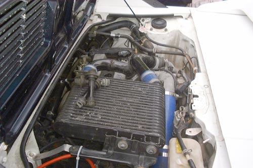
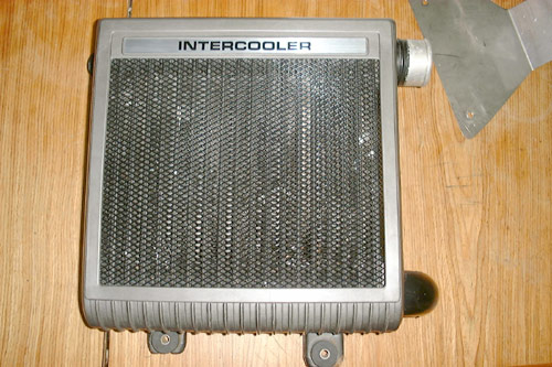
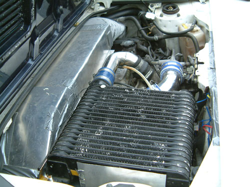
Intercooler immediately post
conversion. Please note that the intercooler here is from a MR2
MK2 Turbo or Celica GT4. This intercooler has fewer cores that are
more tightly packed in comparison with an original MR2
Supercharger. This is because it is designed for a high airflow
mounting position such as in the side engine vent in a MK2 MR2
Turbo. The MR2 Supercharger intercooler has more channels spaced
further apart indicating it's design for a relatively low air
flow.
My first step in improving the
intercooling centred on finding an original Supercharger engine
lid which is fibreglass and has two raised vents (you can see it
in the above picture). One of these vents is basically a dummy,
but the other one seals to the top of the intercooler. I also
sourced an original SC intercooler, but the problem was that as I had
an AE92 spec engine which came from a front-wheel drive Levin the
outlet pipe from the supercharger was different, so I didn't have
any of the corresponding pipework to plumb the intercooler in.
Realising that it'd be very difficult indeed to source these I
elected to have the necessary parts made by a local exhaust
specialist in stainless steel. Richard at JP
Exhausts was very helpful and as Mark has two original
MR2 Superchargers and an engine in bits I was able to lend Richard
at JP the original bends to copy.
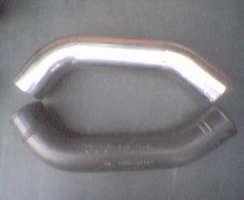
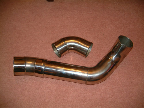
Low res. This is the lower pipe that connects to the supercharger
outlet to the intercooler. The black pipe is the plastic original
used as a template.
This is the intercooler to inlet manifold pipe. Again the black
plastic pipe is the original which was used as a template.
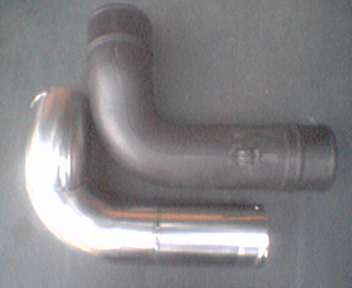
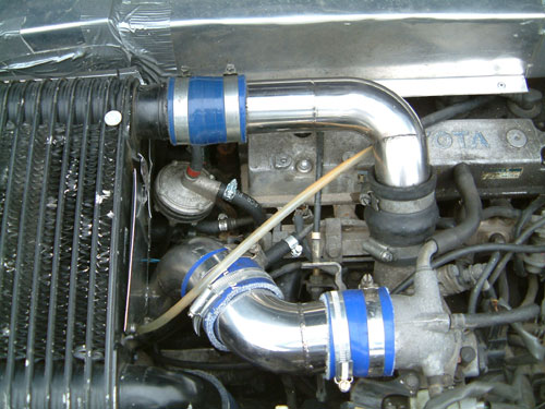
I had to get a supercharger outlet pipe made up as well which
involved having a flange to mount to the supercharger laser cut
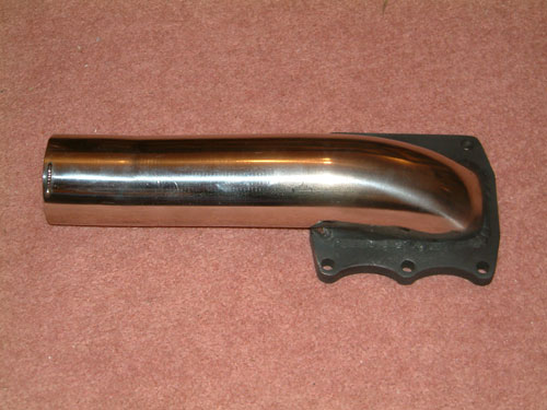
Really nice bit of work by Richard at JP. This is the supercharger
outlet pipe. On the original outlet pipe which is in alloy, there
is a branch that comes off to go to the ABV valve. As I am running
above standard boost pressures there is no need for this, so
effectively an outlet of this design ensures that all boost goes
to the engine!
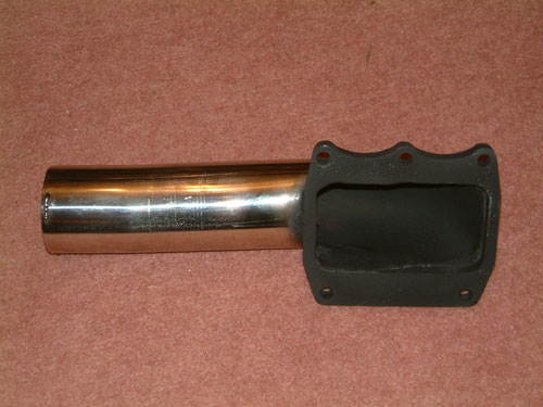
Another view of the supercharger outlet pipe.
Another problem I encountered once I had the intercooler in
place was that it was fouling my induction piping which is in
Samco hose that goes to the air filter in the boot. Back to JP
again this time with Mark's OEM induction pipe to be copied to
give enough room for the intercooler.
Very sexy pipe work though because the original Toyota induction
pipe has a very sharp bend onto the throttle body in rubbery
plastic, this can't be recreated in stainless so cutting back the
throttle body was the only option.
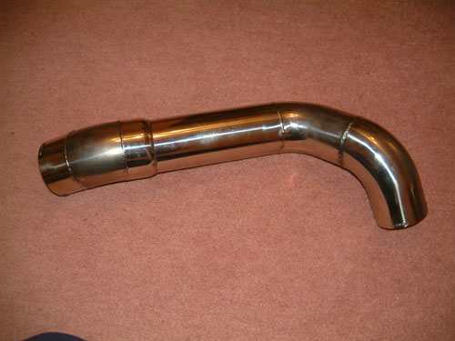
Another view of the induction pipe work clearly showing the
reducer from 70mm to around 65mm.
Original supercharger intercooler
with cover in place
With all the shiny pipe work and
intercooler in place, intercooling was improved but still nowhere
near good enough for track work. My plan all along had been to
fabricate ducting from aluminium in an effort to seal the
intercooler from ambient heat within the engine bay. The plan was
to duct air from the engine side vent over the cam covers then
down and up through the intercooler. The intercooler would be
sealed to the engine lid, so as to help increase the effect by air
being 'sucked' out through the intercooler by the low
pressure area above the engine lid. To further aid airflow through
the intercooler I also manufactured a side scoop which would help
force more air into the ducting. The engine bay fan is permanently
on which should provide a nice cooling effect on the intercooler
when not moving.
Flexi-hose was used to pick up air from behind the fan and to
connect to the ducting, thus allowing engine movement.
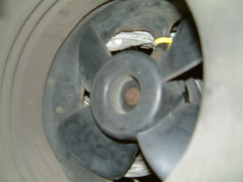
This is the engine bay fan. You can see the flex-hose immediately
behind it .This does not cover the entire area behind the fan as I
wanted to allow some air to still get to the engine bay for
cooling.
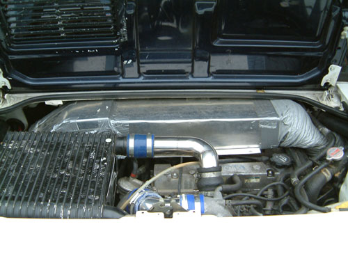
Intercooler ducting is in fact finished in this picture. At the
top of the pic, the flexi-hose can be seen. The ducting goes over
the exhaust cam cover and then down and underneath the intercooler
to which it is sealed. Aluminium is riveted together and sealed
with industrial double sided tape that forms a sandwich between
the joints of aluminium and is then pop riveted through where it
is under structural stress. The intercooler when removed has the
ducting attached to it, but will slide out from the ducting over
the cam covers.
A clearer pic of the flexi-hose which is tie wrapped to the rear
of the fan. Intercooler stainless outlet pipe can be seen
immediately in front of the duct.
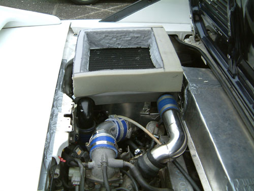
Foam is used on top of the intercooler to seal it to the engine
lid. Really the intercooler should be higher but I had problems
raising it enough and elected to use the foam as a temporary
measure for test purposes. Induction piping from shortened
throttle body can be seen to the left.
Yes I know, what beautiful pipework. Sometimes functional things
really can look the part. A good advert for JP
Exhausts I think! Bottom pipework is induction from air filter in boot to shortened throttle body. Position of
temperature probe can be seen at top right of intercooler (white
disc)
So does it work? Well previously
on-track at Spa and on cruising at 90mph the temperature
went off the scale which is limited to 70C after a lap or so of
the circuit or around 10minutes of cruising on the motorway. With
the ducting on temperatures were stabilised at just under 50C.
This could literally be a halving of the intercooler temperature!
The car felt much, much better on track as with the heatsoak under
control power didn't noticeably drop off. See
Beard pt 3 for the Side Scoop.
Furthermore temperature was reduced to near ambient when just
idling with the engine vent fan running within a few minutes. I
actually experimented running on the M62 at around 90mph. The M62
is the highest motorway in England and has some steep inclines.
Temperature never rose above 32C. On the M1 I tried cruising at
around 70mph without the supercharger running. Temperature came
down to within 2 degrees of ambient after 15minutes and could be
seen to drop a degree or every minute.
Mark has just received a proper
temperature module that is faster reading and more accurate as
well as allowing two probes to be inserted into the intercooler
inlet and outlet. This will give us a much better idea of
intercooler efficiency and the effect of the ducting than the
cheap Halfords special which is simply placed on top of the
intercooler outlet.